Creating interior using 3d max
Hello, in
this tutorial I will show one of the ways one can create an interior scene
having a drawing. Drawing might be as a picture, e.g. jpg, bmp, tiff, or any
other bitmap picture format.
Ok, let’s
start. Open 3ds max and switch to top view.

Enable
Material Editor and choose VRAY MLT material and set the picture of our
premises as its texture.

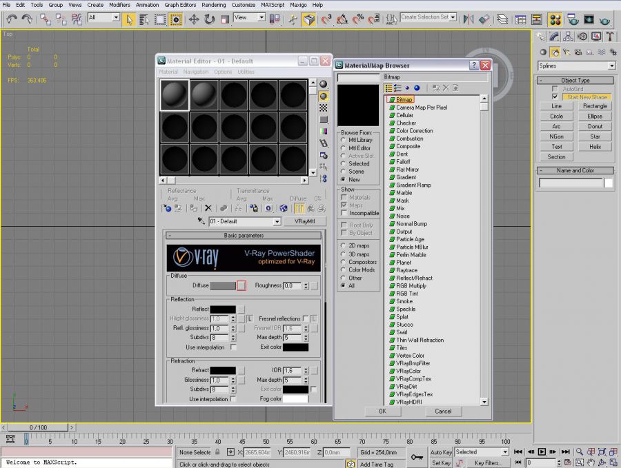
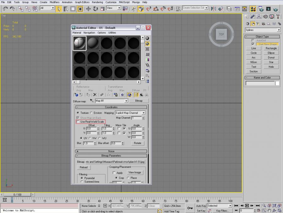
Find out
the resolution of our picture by reading the bitmap’s properties with either Windows
explorer or your favorite viewer. Create
a plane of the same size as your picture in pixels.
After this,
assign created material with texture of the premises to the plane. Apply UVM
Mapping modifier to the plane with the settings below.
Set Mapping
to Planar and disable Real-World Map Size.

Having done
so, we might already have sharp picture of the plan of the premises. If it not
sharp enough go to 3ds max’s settings: Customize – Preferences…
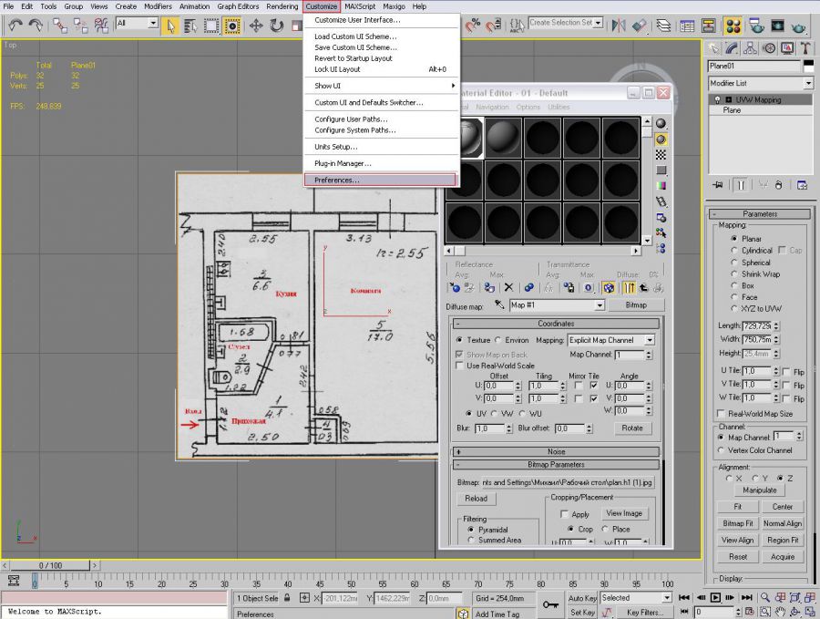
Choose
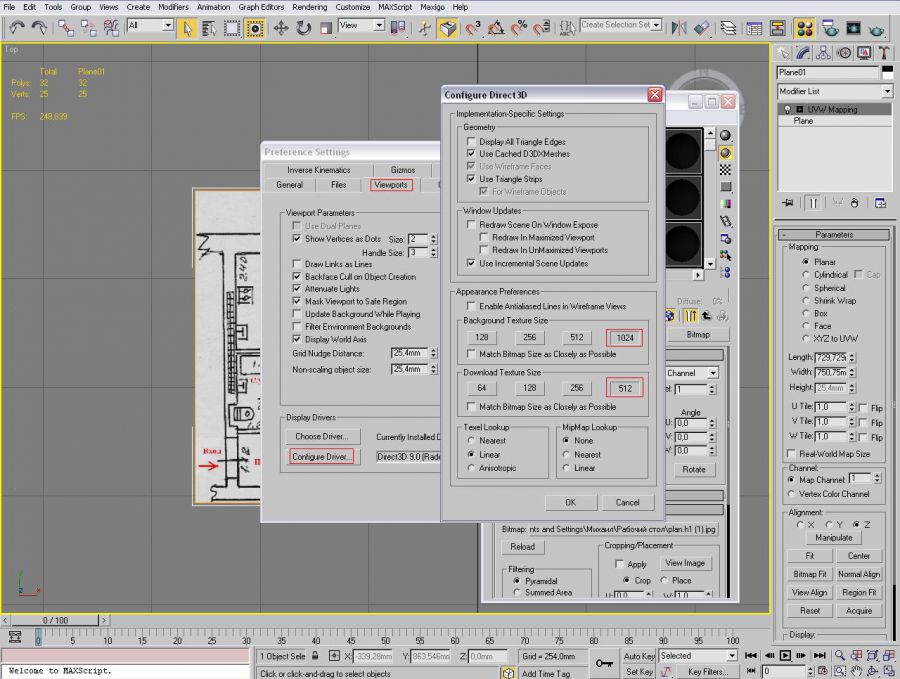
Viewports tab and press Configure Driver… This is where we can choose the
textures quality, which are viewed on the scene. Specify maximum available
value and return to the scene. Perhaps you might need to save the scene and
restart 3ds max, if there won’t be any effect.
Ok, if
everything went well, and the premises plan is clear to see, we can go on.
Let’s take
the longest side of our premises. It is very important that there is a size
specified for it. Create a rectangular with the length of the side’s size. Its
width can be of any size.
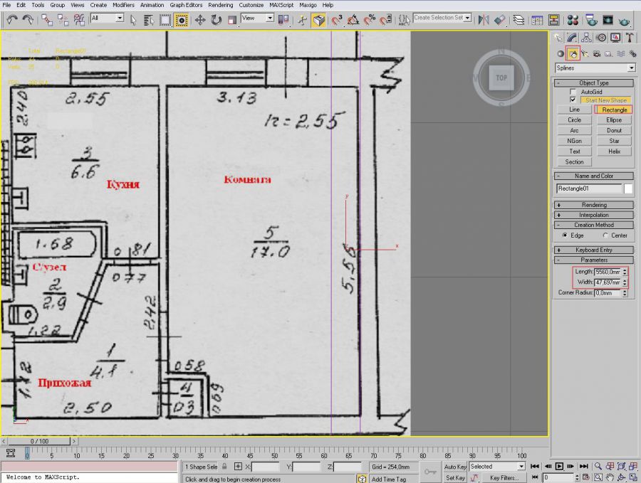
Now we have
to make our plane of real dimensions, so the plan could be viewed in 1:1 scale.
Of course you won’t make it accurate till the millimeters, but you don’t have
to for visualization of the premises. Select SCALE instrument and try to make
the size of the plane in the way that the sizes of the longest side of the
premises and the length of the rectangular are the same and fit. If it will not
be suitable, you could lower the plane a little bit down by the Z axis. So that
rectangular is on the top of the plane. All of this should be done in TOP view,
so you won’t be misled be the perspective view. For more precision you could
use the slider, which sets the scale’s parameters. It allows you much more
precise setting than with the use of mouse.
When the
sizes have been fit select Create – Line and outline our room with it. If the
lines aren’t straight, because e.g. the plan has been drawn so, I would suggest
to ignore it and make them straight and with 90 degree intersections. Otherwise
it might later cause some issue while rendering. If you still got one line not
straight, it is most likely you will after the first try, you can select a
segment and align the side so it intersects with others with 90 degree angle.
In my case I have to pull it by the Y axis till the side is straight.
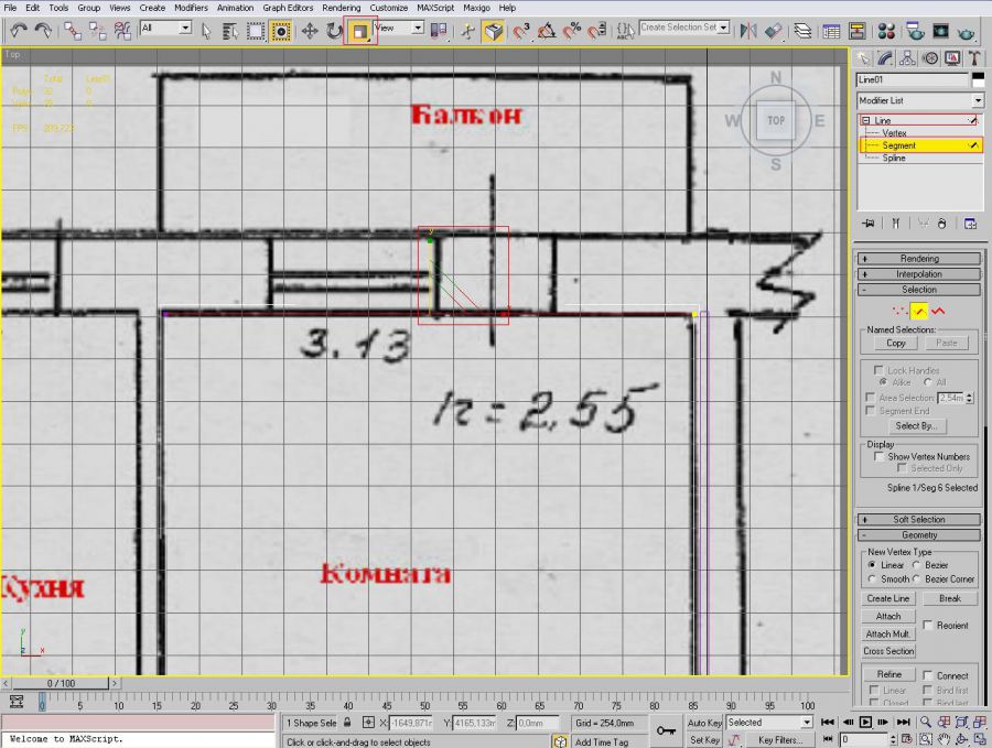
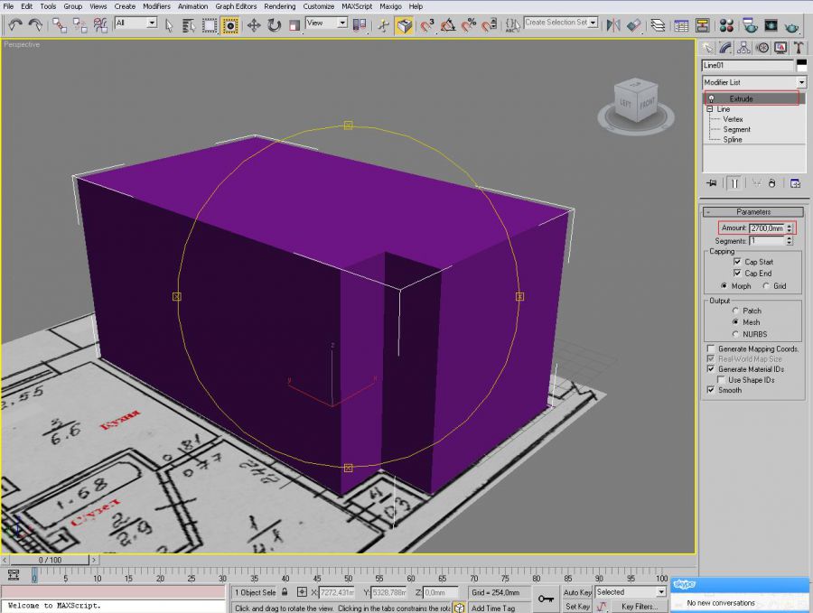
Use Extrude
modifier on the line. Set the height of our room as the Amount value. After
this we will have solid room.
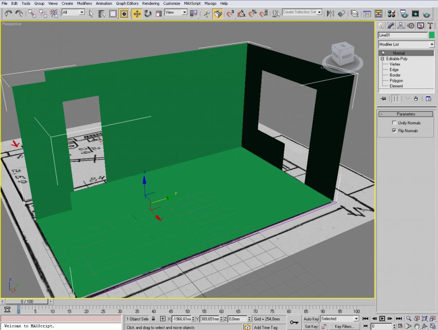
Convert the
object into Editable Poly – by the right click on the object and choosing
Convert To – Editable Poly. After this conversion use Normal modifier, which
will make the object in-side-out, this would make the further work with it far
more suitable. Next step is to do windows and doors in it. To do some edit
Editable Poly – go to polygons editing mode, when you choose it will be
highlighted with the yellow.

Firstly you
have to choose the right wall (polygon).
Select
Slice plane instrument, it will slice the plane where we need it. Take a look
at the plane where the doors and windows are places, set the slice plane where
needed. And every time you press the Slice button the polygon will be cut by
the Slice plane.
Secondly,
choose another polygon where the door should be and slice it the same way as
before.

When the
markings is done, we now can delete unneeded polygons, select them and press
Delete key. Now we have holes in the places where door and window should be.
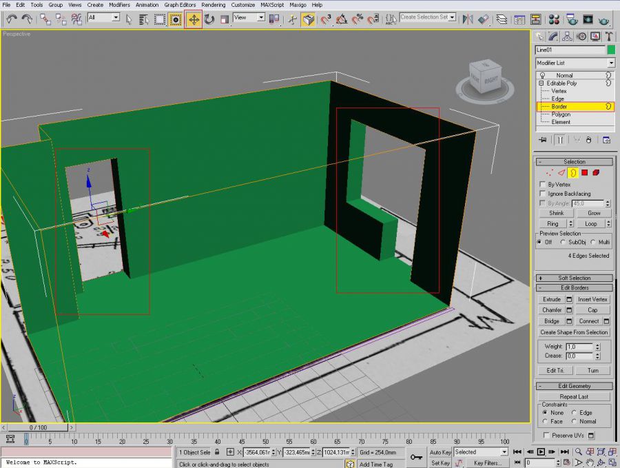
Go to
editing mode for Editable Poly – Border, select the window, press Shift and
pull the mouse for a certain depth. Do the same with the door. As a result we
have a room where we can install a window and a door.
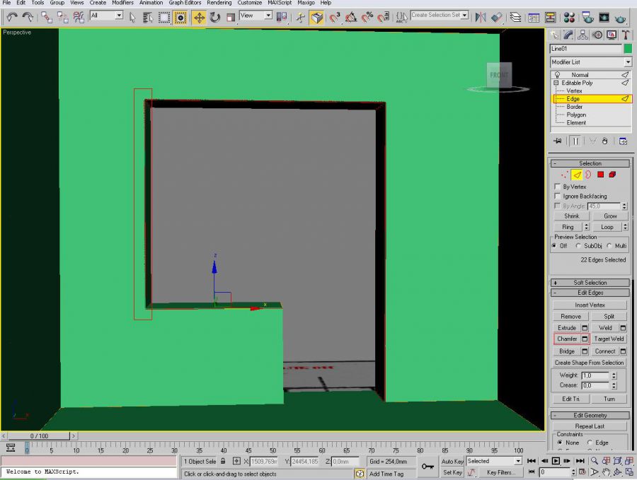
Additionally
for better visualization you could make some chambers. Select Edge mode in Editable Poly, choose the
faces which correspond to the angles in the room’s interior and apply Chamber
to them, say 5 mm.
We can now
finish this tutorial. The advantage of this method is that it is very fast and
useful for modeling premises when you have a plan of the building.


Merhaba ... 3DS ile çalışıyor musunuz?
Hola ...trabajas con 3DS¡?